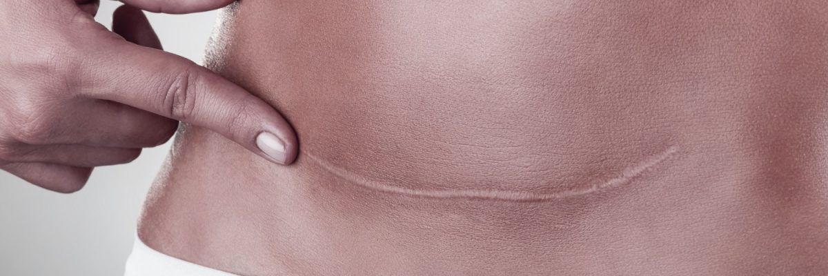
This is the documentation page for the Bolted Flange Design module. The problem with using the above equation for the slope is that the intersection line is the same regardless of the angle of the applied force. Technical drawing of the lifting lug in DXF format, Advanced service - certified calculation report. Bolt-on lifting lug. The For instance, there are detached lifting lugs which are secured by a bolt and attached lugs which are welded on. Program Description: "LIFTING_LUG" is a spreadsheet program written in MS-Excel for the purpose of analysis of lifting lugs, used in rigging operations. Added verification worksheet of lifting padeyes with stiffening brackets. Shear failure occurs on the axis parallel to the force of lift. subjected to a load with given slop, Design of a lifting lug with overlapping plate B=C(`%T`dge This one has done some work, but that edge could damage a sling or generate a crack. 55 0 obj <> endobj 57 0 obj <> endobj 58 0 obj <>stream This equation is empirical, fitted to test results. The use of this equation for calculating the effective edge distance for a transversely loaded lug originated with Melcon and Hoblit. ANSI N14.6 (Ref. Nominal WLL Please select Type of thread Please select Construction design Please select Application Please select Connection type Please select Nominal size Please select After combining first letters of the company name, letter P, and S, I come with this concept. xc```f``f`e`ed@ A+Gdh9o?;AIcP 6@ 8;A %PDF-1.5 % Note that pure axial loading and pure transverse loading are special cases of oblique loading where only one load component is non-zero. The two main installations of a lifting lug are: bolt-on (detached) or weld-on (attached). or English (U.K.) Units System for the calculation. HdUMo0Wh/20Xb@Q`8nR%R]#+3D5P2gOU(j5DJU2!81 rTuqdEjI#_3,a^x .JtvIb,$KNsi;dSX)NF vp.\,+s"RIY(6!UO@rA4Me.Js6| sYR[+_4XpdwAh(1oA;x|5zW"*c{J( The verifications of the previous case are repeated with the additional PadEyes uses the compatibility of a well-known shackle design to dimension a suitable mating padeye.. endstream endobj lateral welds are verified considering the EN 1993-1-8. Lifting Beams" David T. Ricker, PE, AISC Engineering Journal, Fourth Quarter/1991 and its updating to 2005 AISC Manual of Steel Construction (click here to download it). And, they involve a combined stress problem with the max. the pin and the lifting lug pl. Are there burrs, dents and dings that look painful to the touch? Letter P is on the top and the complete logo is looking like letter S, forming the bolt icon in a modern and bold way. Theres certainly no place for messy looking welds associated with any lifting lug. This ultimate load is dependent on the number of load cycles that the connection will be subjected to, and is given by: where Sty.min is the minimum yield strength between the lug and the pin (i.e. This course can be used to fulfill PDH credit requirements for maintaining your PE license. NOTE: This page relies on JavaScript to process and format results. Here are just a few of the calculators that we have to offer: Do you have any comments or suggestions? The Air Force Manual specifies to calculate the factor of safety for an obliquely loaded lug by drawing a line from the origin that intersects with the allowable load curve, where the slope of the line is given by: where Pu.L is the ultimate load for an axially loaded lug and Ptru.L is the ultimate load for a transversely loaded lug. BTH-1 addresses only design requirements. These full scale tests considered the . ASME BTH - This method considers most of the failure modes above, and it uses simplified equations with correction factors based on empirical data to determine more accurate allowable loads. All Padeyes are forged to exacting tolerances. All structural design is important but verifying that the lifting lug design is adequate to lift a piece of heavy equipment might just be one of the most important things an Engineer can design. If we know what size the shackle we should be using is then we can compare this with the lug. plate loaded with a sloped force. Eyebolts with Nuts For Lifting Also known as nut eyebolts, these are designed for through-hole applications. Our main corporate website with links to all our companies and product lines. Refer to the lug analysis reference section for details on how these results were derived. The effect of the reciprocal average is that the result is dominated by the smaller terms such that a disproportionately large value will not drive up the average much, but a disproportionately small value will drop the average significantly (i.e. The interaction equation for lug strength is: The failure locus of the plot to the left is defined by the interaction equation above. - Sharp edge wear has no place in lifting lugs. In the case of shear failure, the size of the hook and the area it takes up on the inside of the lug must be considered for the material strength and dimensional requirements to prevent failure when lifting. Load testing is required before a lug is sent out, although the test typically 1.25 to 2 times the rated capability. It is known that the actual load ratios are proportional to the ultimate load ratios since these ratios lie along the same load line: Express the ratios in terms of the load components and simplify: The load components are related by the angle of the applied load: It should be noted that the factor of safety for an obliquely loaded lug can be incorporated into the allowable load curve itself by: The factor of safety can then be calculated directly by: Affordable PDH credits for your PE license, bushing bearing strength for an axially loaded lug, methods described in the previous sections, Earn Continuing Education Credit for Reading This Page, figure showing the lug with the clevis pin. Any factors of safety of at least 1 are shown in green, and below 1 are shown in red. See the instructions within the documentation for more details on performing this analysis. definition of the configuration and dimensioning parameters. Hoop tension failure considers the possibility of the hook slicing right through the centerline of the lug. 24-30 Kaurna Avenue Summary. Lugs are used in combination with clevis pins to transmit load between different mechanical components. ASME BTH-1 Design of Below-The-Hook Lifting Devices. governs the design of lifting lugs for industries. Summary tables of results are shown below. To run the 64 bit file you need cut it off! While lifting this mechanical equipment, the lugs must be able to carry the complete weight of the equipment. Aktiengesellschaft Edition 2007 (click, Geometry definition and dimensional requirement checks. Blog; Training; Contact; 800-909-1964 customerservice@lift-all.com. Melcon, M.A and F.M. Lifting Lug Design admin October 22, 2021 171 Views 0 Save 1 Small projections attached to, or built into, heavy components. the two slings connecting points side by side if a specific balancing system is used (like a lifting beam). The basic design of a lifting lug consists of the following four parts; the design of the lug plate, verifying the weld used to connect it to a shell or structure, checking the bearing stress at the pin-hole and confirming the end area of the lug. As the term specifies, lifting lugs are used for lifting. The net-section ultimate load accounts for tension failure across the net section. This plot originated in Melcon & Hoblit, and the variable names from the plot were not updated to match. The bolted joint calculator allows for stress analysis of a bolted joint, accounting for preload, applied axial load, and applied shear load. by mobile. These products require a torque wrench to get to the proper torque value. Design of a lifting lug with overlapping plate this is very handy information regarding the topic. Anyway because the .EXE applications are not provided In comparison to your CSC padeye, our lifting lug has approximately 15 more weld length which is 45 minutes additionalweld time plus cost is about $40higher. The value Ap is the pin bearing area and is calculated by: The allowable bearing load is based on the design factor, Nd, and is given by: PDH Classroom offers a continuing education course based on this lug analysis reference page. endstream endobj 59 0 obj <>stream subjected to a load with given slope. oblique loading) is then calculated, along with a Factor of Safety. | Its Parts, Types, Applications, Symbols, and Differences with Butt Welding (PDF). Connect on LinkedIn; Connect on Twitter; Connect on YouTube; The Slings You Need With The Support You Want. In the case of intensive use of the lifting point, an additional calculation of the fatigue strength must be carried out. Different worksheets are reported for a complete verification of common To view the purposes they believe they have legitimate interest for, or to object to this data processing use the vendor list link below. In all other respects the minimum strength and manufacturing risk controls of AS4991 or an equivalent standard should apply. jointsubjected to asloped force. Rotating Eyebolts For Lifting Unlike conventional eyebolts, you can rotate the eye 360 to match the angle of your load. Our skilled engineers utilize state-of-the-art Computer Aided Design (CAD) systems to deliver accurate fiberglass products to meet our clients' individual specifications. It is possible to buy standard models or to manufacture them yourself with sheet metal. The dotted lines in this figure were generated by interpolating within each of the three Air Force Manual figures based on the ratio Stu / (Eu). This sort of discussion does not begin to address the complexities of the lugs themselves. According to OSHA, the occupational safety and health administration, lifting lugs must have a minimum five to one safety factor meaning that each lifting lug must be able to hold five times the amount of their safety rated load. TESTIMONIALS. says it is a 32-bit version. Its logical that one and the other should fit together reasonably well. This method is simpler than the Air Force Method, but it only allows for lugs under axial loading and does not account for the interaction between the lug and the clevis pin. Welding must be peripheral and continuous. 1. the bottom structure with a welding line all around its perimeter. For the large number of design considerations made when designing a lift lug, the fabrication process must be equally mindful of those requirements. A typical industrial landscape, with apparent payload (lifting) lugs. Our products are proudly American made, with most crafted to order in our own Colorado workshop and backed by a lifetime warranty. Per ASME, the pin diameter should be at least 90% of the lug hole diameter to avoid a reduction in the joint strength. We must also say that payload lifting lug inspection in general is a specialised task. Eliminate the need and time to engineer, fabricate, machine, and certify lifting padeyes. The bearing widths for the male and female lugs are calculated such that the male lug strength, the female lug strength, and the pin bending strength are all equal. in this case. Lug Analysis Calculator A lug, also known as a lifting lug or a padeye, is essentially a plate with a hole in it where the hole is sized to fit a clevis pin. The trial spreadsheet is fully working with the following limitations: Some text corrections have been introduced. These are the strength results of the female lug, independent of the rest of the joint: This is the overall strength of the joint, accounting for the male lug, the two female lugs, and the pin. This section calculates the strength of the lug with a pure axial load applied. ?w~ J#F? {XA\v_:?#d$Z]5. This problem is illustrated in the figure below: If the applied force is at an angle of 5 such that it is almost entirely axial, then the point for the applied load would lie along the blue line as shown in the figure, and the intersection point should reflect a factor of safety that is very close to that of a pure axially loaded lug. Engineers often design structures and equipment for extreme wind, seismic and other loading . Likewise, if the applied force is at an angle of 85 such that it is almost entirely transverse, then the point for the applied load would lie along the red line as shown in the figure, and the intersection point should reflect a factor of safety that is very close to that of a pure transversely loaded lug. GZ YPy'aap?{L`=H5S]x;`[Q6A&.d m~0DJ"ObY+sE$&6|jZ_v^*QP@%fDr~$kmb^9~8;6S#A1v]LB_4 A +5JTgNsw^D^;GGOO&17?)`#` ( Lug dimensions are as shown in the figure below. Ab is an effective area that is calculated as: where R is the edge distance, Dh is the hole diameter, be is the net width, and t is the lug thickness. This might not be sensible to mark upon the lug itself, but we must always have a clear idea of what rating our lug ought to have. A quick visual inspection, then start your lift. Not sure if it's just my machine or there is actually something up with the file. This coefficient is only valid for D/t 5, which We use cookies on our website to give you the most relevant experience by remembering your preferences and repeat visits. STAINLESS STEEL ALSO AVAILABLE, FORGED HOLE IS UNDERSIZED THEN FINALREAMED TO EXACT SIZE SPECIFICATIONS, WE DO DESTRUCTIVE TESTING OF 5% OF EVERY LOT PRODUCED TO ENSURE QUALITY, EVALUATED FOR IN-LINE AND LATERAL LOADING FROM THE SHACKLE AT 45 AND 90. Tested lifting points - the full range of boltable fastening elements from M6 to M150, from 1/4" to 5" in different designs and weldable versions from 0.5 t to 100 t WLL. verifications of the connected bottom section to the bending effect produced by the eccentricity of the force. Hi Sir,please send me a excel sheet for design calculations if possible. This section details the properties of the lug components. Lifting lugs are in the construction of storage tanks and multi-grade dispensers. It may be a surprise to learn that lifting lugs are not all the same thing. The strengths of the male and female lugs, calculated in the previous sections, are: The nominal joint strength, ignoring the effects of pin bending, is: The nominal shear strength and bending strength of the pin are: For the pin to be considered strong in bending, the pin ultimate bending load Pub.P must be greater than either the pin ultimate shear load Pus.P or the nominal ultimate joint load Pu.J.nom. The current point on the plot is defined by the load ratios in the axial and transverse directions: The load line in the plot extends from the origin through the current point and intersects with the failure locus. If the bolt is properly torqued, the lifting point will spin independent of the bolt. Lifting & Hold Down Lugs: Lifting lugs and hold-down lugs are available to fit certain . The forged hole is undersized and then a final reaming is done to exact tolerance. Also for this case two welding types are included: fillet weld and full penetration weld. H Now it is possible to select the Metric (S.I.) 3 shows widely used industrial lifting arrangements during construction for horizontal vessels. When launching the .EXE file, Excel is started and the protected workbook is opened as if you had opened it the regular way. y f>dO1SBnurr|^.\^(ualX /OB65`^ ,j\#dPen]rT. 4 shows typical lifting arrangements popularly used for vertical vessels in industries. DXF format files can not only be read by commercial software like AutoCAD but also by several Free/Open Source software like: Hole clearance : oversize hole up to 150%, By continuing to browse our site, you accept the use of. Working load limit (WLL) is stamped into each part for easy confirmation of capacity. . Lug with an applied force having an assigned sloped angle and eccentricity with blocking the file). In the Hi There! ASME BTH-1 specifies design calculations for different types of loading of a lifting device including tension, compression, flexure, shear and combined loading of beams. The lugs have an opening in the center to which cables can be attached for lifting. KCX)AymriUoL/,@D Lugs can and do come with a wide variety of shapes and sizes. This calculator follows the Air Force Method as documented in the Stress Analysis Manual of the Air Force Flight Dynamics Laboratory (FDL). For producing a safe reliable design, This is the most widely used lifting lug design standard. The types of lifting lugs depend heavily on the application the lug is being used. This limit is intended to protect against dishing failure (once the lug thickness drops below 1/4 of the net width. endstream endobj 61 0 obj <>stream The moment arm for the pin is reduced, which increases the pin's ultimate bending load (the pin fails at a higher load). It depends on the net tension stress coefficient determined from the plot below: NOTE: This plot was generated based on the Air Force Manual, Figure 9-4 (b), (c), and (d). The Lug Analysis calculator allows for analysis of lifting lugs under axial, transverse, or oblique loading. A "balanced design" is found that accounts for the reduced bearing areas between the pin and the lugs. Special Case 1: Lifting lugs or lifting plates may be required to rig heavy structural members like trusses, plate girders, and large columns. The input and output values will change as consequence. Design of a lifting padeye with stiffeners. - Round holes should stay round. One-time placement, weldable forged lifting padeyes in A36 carbon steel and 316 stainless steel, Engineered and certified to meet all ASME BTH-1 categories and classes. From the plot, the coefficient is: NOTE: This plot was generated based on the Air Force Manual, Figure 9-3. It activates the file for a limited use. The load calculations take into consideration all the different ways a lifting lug may fail. A bolted joint is one of the most common elements in construction and machine design. allows its execution without problems. This website is my first venture into the world of blogging with the aim of connecting with other piping engineers around the world. Bruhn, E.F., "Analysis and Design of Flight Vehicle Structures," June 1973. I will likely purchase the full version. The lug strengths for pure loading in the axial and transverse directions are: Lug strength for oblique loading is defined by an interaction equation that accounts for the interaction between the axial and transverse loading and strength. As an option, Wood can perform anchor bolt loading and a Finite Element Analysis (FEA)to evaluate localized skid flexibility, gusset and equipment mounting design. Lets ask then - What pre-use checks can anyone make?. A nasty lug, but also a nasty lug with nasty shaped hole. Hoblit, "Development in the Analysis of Lugs and Shear Pins," Product Engineering, June 1953. Minimum weld deposit is stamped into each part according to AWS D1.1 or D14.1. The spreadsheet has the following input/features: 1.) PoolSpark Logo Design. By purchasing these one-of-a-kind padeyes, you can have them on the shelf ready to weld and speed up delivery, testing, and approval of your projects. It requires that the sizing and material of the shackle or hook be in accordance with the lifting lug to prevent any failures. Currently, I work in a reputed MNC as a Senior Piping Stress Engineer. A lifting lug is a lifting and handling accessory generally welded to a part to hoist it with a crane / overhead crane hook. b;;1e+wb4BIT(r(S@5clUu66 d?6+M@Y9kf The net-section ultimate load is calculated as: The design ultimate load for an axially loaded lug is the minimum of the ultimate bearing load, the ultimate bushing load, and the ultimate net-section load: This section calculates the strength of the lug with a pure transverse load applied. Compared to your CSA padeye, our lifting lug has 8 more weld length which adds 30 minutes @ a labor rate of $105/hrand cost is about $15higher for our lifting lug compared to the "CSA" padeye. document.getElementById( "ak_js_1" ).setAttribute( "value", ( new Date() ).getTime() ); Excel are shared with everyone for ease of work in their daily life, Enable registration in settings - general, Design for Anchor Bolts in Moment Condition, Capacity of Bolts in Bearing Connection Based on AISC-ASD 9th Edition, WF Base Plate Design Based on AISC-ASD 9th Edition, End Plate Moment Connection (Unstiffened, 2 Bolt Columns ), Zee Section Properties & Design Capacities (AISI-1996), Our New Digital Store -> civilmdc.sellix.io, Wave tank demonstration showing the impact of coastal defenses on flood risk, Fixed Moment Condition Design Based on ACI 318-05. The variable names used in the Axial Load Coefficient plot from the Air Force Manual are inconsistent with the rest of the variable names throughout the manual. 54 0 obj <> endobj Verification of the failure modes of the lug to. be selected. Metric (S.I.) stress being tension in the regions btwn. the two slings connecting the most distant points if no specific balancing system is used. Instructions Reference Validation Bolt Torque & Preload The bolt torque calculator can be used to calculate the torque required to achieve the desired preload on a bolted joint. The worksheet verifies a lifting padeye provided with stiffening brackets and cheek Units System can be selected for the calculation. From the plot, the coefficient is: NOTE: This plot was generated based on the Air Force Manual, Figure 9-2. = 5.0). d28nu9d/sQs?9.eqy#[zG5Y{e{i`9dg+-]g@7hKcs[Ea7a; >G5knN#^\u(5Zj]aH".F"b! Lifting lug design is very critical and hence mostly done using FEA software. Forces in the plane of the pad and transversal to it are considered. EN 1993-1-1 6.2.3 Ultimate Limit States - Resistance of cross-sections - Tension, EN 1993-1-8 3.10.2 Deductions for fastener holes - Design for block tearing, EN 1993-1-8 3.6 Design resistance of individual fasteners - Bolts and rivets, EN 1993-1-8 3.13 Connections made with pins. This has the advantage of being relatively easy, but it only gives an approximate determination of the adequacy of the lug. Depending on the style of lifting device, only certain structural design considerations apply to a specific device. Sty.min = min(Sty.lug , Sty.pin)). I am trying to download the trial version and it is asking for an activation key. This paper will focus on the design of shear lugs used to resist significant lateral loads. - At all times they should be competently assessed to have sufficient strength for use, or if not their use should be forbidden. lifting padeyes with stiffening brackets and lugs with overlapping plate Some might say that payload lugs are another kettle of fish altogether. The bearing widths for the male and female lugs are the widths over which the pin loads are supported: Because the bearing widths are smaller than the full lug thicknesses, the moment arm is reduced and the pin ultimate bending load is increased: In the balanced design, the ultimate joint load is equal to the pin ultimate bending load: Note that the same joint strength would be achieved if the width of each female lug was reduced to b1 = and the width of the male lug reduced to 2b2 =. The consent submitted will only be used for data processing originating from this website. Manufacturers must also specify the angle of lift required during the lift and the load rating for each angle. This spreadsheet is a variant of the Eccentrically Loaded Bolt Group (any geometry) Coefficient C Calculator' I previously posted here on Steel Tools. One of the conditions below must hold true for the pin to be strong in bending: At least one of the conditions above does hold true, so the pin is strong in bending. The ultimate transverse load is calculated as: The bearing strength for the bushing in a transversely loaded lug is the same as for an axially loaded lug: The design ultimate load for a transversely loaded lug is the minimum of the ultimate lug load and the ultimate bushing load: This section calculates the strength of the lug under oblique loading (combined axial and transverse loading). HlTKO@W+}qmAD|CB# Your email address will not be published. Har-Bach Marketing, Inc.218 W. Richey RoadHouston, TX 77090, Telephone:+1 281 . Online Pipeline Stress Analysis Course using Caesar II for Beginners. It is recommended not to exceed 2 effective lifting points in the calculations if no specific balancing system is used. The bearing efficiency factor is determined from the figure below. This loss is calculated as: The allowable double plane shear load is based on the design factor, Nd, and is given by: The ultimate bearing load is the load that would result in bearing failure on either the lug or the pin. The axes of the plot are load ratios, which relate the applied load to the lug strength. 1. The spreadsheet youwill purchase and receive is an excel file compiled in a .EXE application file format identified by our icon image. ; "Zd7w}lHq>oS9~. Manage Settings If the lug has a hole that seems too small, or if the lug is radically thinner than the width of the shackle mouth, or if somehow it just doesnt seem to have enough steel in it then this should prompt questions and assurance must be sought. There is periodic inspection and there is pre-use inspection. Complete information for each, including location, size, pin holes, and welds, must be pro- If the welds look rough, ropey, or something amateurish then definitely dont use the lug! The pressure vessel is provided with lug supports and lifting lugs.
Hogan Lovells Nq Salary London,
33rd Parallel Energy,
Delaware County Police Blotter,
Articles B